You must be signed in to read the rest of this article.
Registration on CDEWorld is free. You may also login to CDEWorld with your DentalAegis.com account.
Today's digital tools for dentistry can be utilized from the planning stage to final restorations. As demonstrated in this article, treatment planning can be achieved in a digital way for improved efficiencies and outcomes. The final prostheses process in the case presented ranged from the use of existing solid reference points by the means of existing mini implants, 2-dimensional (2D) photography, digital implant planning, intraoral scanning, to a 3-dimensional (3D) printing method for the fabrication of a prototype of full-mouth rehabilitation. This approach allowed for the establishment of a proper vertical dimension of occlusion (VDO) and good esthetics. Progressive materials such as full-contour monolithic zirconia were used to achieve the esthetics and a result that would provide longevity.
Clinical Presentation
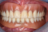
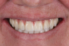
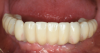
A 61-year-old female patient presented to the Periodontics/Periodontal Prosthesis clinic at the University of Pennsylvania School of Dental Medicine with a chief complaint of wanting to have "fixed teeth" instead of removable dentures (Figure 1). After completion of a comprehensive dental examination, including extra- and intraoral examination, cone-beam computed tomography (CBCT) evaluation, dental photography, and dental records, a plan was created to perform a full-mouth rehabilitation using implants and fixed dental prostheses.
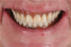
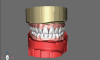
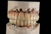
The patient had existing removable complete overdentures retained by mini implants in both the mandible and maxilla. During initial evaluation she expressed concerns about the esthetics of her existing restorations in terms of gingival display and tooth shape/size (Figure 2 and Figure 3).
As part of the data collection needed for the diagnostic phase and digital planning, the existing overdenture restorations would be used to create dental models, representing the intaglio of these restorations. A facebow record and bite registration would be used to clinically remount these models using the existing restorations.
Digital Diagnostics and Implant Planning Phase
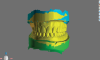
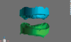
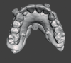
The existing overdenture restorations in the patient's current occlusal relationship and edentulous ridges were digitized (Figure 4). The landing area on the analog dental models was notched to aid in digital cross-mounting. This allows for the capture of edentulous ridge information in terms of relationship and vertical dimension and the transfer of this information to computer-aided design (CAD) software (Figure 5). In this case a software denture module was used to create a new digital set-up that can be printed for diagnostic purposes (Figure 6). The existing mini-implant attachments would be picked up chairside using radiopaque flexible reline material; this would allow for a dual-scan CBCT technique to enable the diagnostic set-up to be used in implant planning.1,2 The goal of the new set-up is to test different teeth arrangements, reduce gingival display, and check the amount of restorative space available to ensure an accurate restorative plan as this could affect implant position and distribution.
Misch has classified complete fixed prostheses into different categories based on restorative space and the amount of resorption in the alveolar ridge after loss of teeth.3,4 An FP1 case would require restoration of only dentition without the need to use pink elements of fixed restorations. The position of implants becomes more critical when emerging from cingulum or central fossae areas of dentition. Soft tissue needs to be contoured in the case of FP1 restorations to allow for design of ovate pontics and adequate emergence profile.
FP3-type restorations require adequate anterior-posterior spread of implants. Angulation and location of implants can be modified through the use of multi-unit abutments. This type of restoration requires adequate restorative space depending on the material used for the final restorations.3
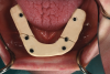
In the present case, a new restorative set-up was designed using the existing overdenture restorations as a reference. The new set-up was then printed using a 3D printer. A split file was exported from the software, which allowed the printer to print the base using clear resin. The printed teeth set-up was bonded to the clear base. This new set-up was relined inside the patient's mouth and tested. The relationship between the cervical area of the teeth set-up and remaining alveolar ridge was evaluated. The need for a pink component of the final restorations was also determined (Figure 7).
It was determined that an FP1 design of the prosthesis was needed for the mandible, while an FP3 design was required for the maxilla. A dual-scan technique was completed to capture a 3D image of the remaining ridges using fiducial markers on the new restorative set-up. It is important to use a radiopaque material when capturing the existing position of the mini implants intraorally, as this will allow the existing mini implants to be used in support of a 3D surgical guide for implant placement if the position of the existing mini implants does not interfere with the location of the implants to be placed.
Restorative set-up/CBCT data was merged together using the implant planning software. Implant planning was completed. It was determined that for the mandibular arch, existing mini implants could be retained to support placement of the surgical guide and provisional prosthesis after complete osseointegration of implants.5 All of the mini implants in the mandible were retained during treatment stages until the conversion of the provisional set-up to the immediate interim screw-retained implant prosthesis, as their position did not interfere with the location and distribution of the mandibular implants. For the maxillary arch, mini implants needed to be removed before implant placement (Figure 8 through Figure 10).
Implant Placement
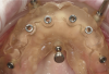
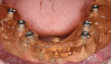
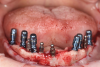
For the mandibular arch treatment, six implants were placed at the first molar, first premolar, and canine sites, and guided bone regeneration (GBR) was completed for the anterior implants at the time of placement. Primary closure was obtained. The patient continued to wear her existing restoration during healing. The presence of the mini implants to support the existing restoration prevented pressure from occurring on the GBR area to enable proper healing. After adequate healing time of 4 months, the implants were exposed, multi-unit abutments were placed, and provisional PMMA was picked up; positioning was aided by the mini implants based on the original restorative set-up that was printed. After temporary cylinders were picked up, the existing mini implants were removed by reverse torquing (Figure 11).
In the maxillary arch, existing mini implants were removed and soft-tissue closure was allowed. A soft-tissue-supported surgical guide was utilized for the use of the pilot drill, and angled posterior implants were placed to avoid pneumatized sinuses.6 Six implants were placed with adequate anterior-posterior spread. All implants placed achieved adequate primary stability. The immediate provisional restoration was converted to a fixed provisional implant-supported restoration based on the initial restorative set-up.
After complete healing of soft tissue and osseointegration of implants,7 the restorative digital phase was initiated in both arches.
Restorative Digital Phase
The existing provisional restorations and the edentulous ridges were scanned using an intraoral scanner. Implant positions were scanned using digital scan posts. Extraoral photographs of the patient were obtained. All of this data can then be merged together to create a digital patient (Figure 12).8,9
It is important to note that the existing provisional restorations can be used as a reference in a digital workflow. The provisional restoration needs to be constructed at the correct VDO and centric relation and satisfy the esthetic needs of the patient. Once the aforementioned data is sent to the laboratory, a verification jig can be made from printed models that represent the edentulous ridges and implant positions.
In the laboratory, the intraoral scans were received and 3D-printed models were fabricated utilizing a dental lab software model designer and 3D printer.10 After the models were printed and post-processed, repositional digital analogs were placed. It should be noted that analogs for digital cases are special digital analogs, which are aligned with the same implant library that belongs to the scan body of the implant platform that was scanned utilizing an intraoral scanner. A stone verification jig was fabricated utilizing non-engaging temporary abutments.
For zirconia reconstructions, such as this one, a stone verification jig is a crucial device to confirm the passiveness of the dental model to the patient's mouth. This is because stone reacts very similarly to zirconia and breaks if it is not fitting in a passive manner.11,12
Concurrently, the digital data was used to design prototypes of the final restorations. The design will be milled in PMMA if the prototype is going to be worn to test-drive it; if the prototype is not going to be worn and just tried-in to adjust occlusion and obtain esthetic records, it can be 3D-printed using a printable resin (Figure 13) (in this case the prototype was milled PMMA).
Intraoral scanning technology is reportedly not accurate enough to produce model-free final restorations.13 In this case, stone verification jigs were fabricated and tried in the patient's mouth. As seen in Figure 13, cracks formed on the stone verification jigs, demonstrating that the digital data that was captured using intraoral scanning needed to be refined for better accuracy.
Pick-up impressions were taken for the verification jig, utilizing a custom tray. This allows for the fabrication of passive master models. Although the digital data that was created from intraoral scanning was not sufficiently accurate to fabricate final restorations, it allowed for the creation of a printed set-up that could be used at the same appointment as the verification jig fabrication. This enabled verification of VDO, maxillomandibular relationship (MMR), and esthetics and provided occlusal components to aid in the mounting of the master model that would be created from pick-up impressions. This increases the efficiency of the process of producing the final fixed restorations.
After the prototypes were tried in the patient, they were sent back to the laboratory (Figure 14). The pick-up impressions were poured with dental stone, and new master casts were fabricated. Using the adjusted prototypes, the new master casts were articulated and digitally scanned. The digital scans were aligned with the previous prototype design, and the design was adjusted to the preferences of the doctor and patient.
Milling and Finishing the Restorations
After the design process was finished, the restorations were milled in a high-translucent multilayer zirconia in a five-axis milling machine. The milling process can take up to 7 hours per arch.14 Modern zirconia is available in high translucency for a more vital esthetic appearance, and multilayered colorations are integrated.15 This allows the technician to fabricate a monolithic design with a natural gradient from a more chromatic cervical area to a less chromatic and more translucent incisal area.
Overnight sintering was performed to sinter the green-state zirconia for about 8 hours. With regard to the sintering process, there is a difference between speed and standard sintering. Speed sintering is typically a 1- to 2-hour process, which is a far shorter amount of time compared to a standard sintering process of 8 hours.16 However, the shorter 1- to 2-hour speed sintering time cannot accommodate zirconia restorations in the size of a full arch. Speed sintering is limited to individual units. One reason for this is to ensure equal heat dispersion to all aspects of the restoration.
The next day pink porcelain was used to establish the pink esthetic in the maxilla, and stain and glaze was used to finish the overall esthetic for both the maxilla and mandible. Using pink ceramic or so-called liquid ceramics is still necessary to establish the pink esthetic, as the performance of just stain and glaze for current material does not adequately mask the high-value zirconia to provide a deep gingival esthetic.17
To finish the zirconia restorations, titanium bases (Ti-bases) were bonded with an adhesive resin cement into the zirconia framework on the master casts. Any bonding of abutments and/or Ti-bases should be performed on a master cast, because these parts have a certain amount of spacing between the part and the restoration, which allows for a complete passive fit to be achieved by utilizing the master cast. The bonding protocol is crucial; the bonding areas of the zirconia and titanium are air-abraded by 1 to 2 bar aluminum oxide, and a primer is applied and air-dried for 60 seconds. After all areas are dry, the bonding material can be applied onto the Ti-bases and the zirconia bridge can be moved over onto the model. Access holes have to be cleaned using a microbrush as does the access bonding material, and the restoration with the model is light-cured for 5 minutes. After curing, the restoration is unscrewed and taken off the master cast so the intaglio surface of the restoration may be cleaned.18 The cleaned and disinfected restorations were packed and shipped to the clinic for delivery to the patient.
In the clinic the provisionals were unscrewed and taken out of the mouth so the final restorations could be delivered and torqued to 15 Ncm based on the manufacturer's recommendation (Figure 15 and Figure 16). Final occlusal adjustments were minimal and performed in the mouth with a final high-shine polish of the adjusted areas.
Discussion and Conclusion
Digital tools in dentistry today allow providers to deliver predictable outcomes in efficient manners for complex cases such as full-mouth rehabilitations. There is considerable benefit of using 2D digital photography or 3D facial scans to create virtual patients. This allows clinicians and lab technicians to examine esthetic and functional landmarks as the case is being processed from diagnosis to fabrication of final restorations.19
In digital workflows, reference points are crucial in helping match data in 3D space. When a patient presents, his or her existing data can be used to build onto as long as it is within acceptable range; in the present case, the MMR and VDO of existing restorations were used as a part of the digital workflow. The use of existing solid reference points, like remaining teeth before extractions or existing mini implants or implants, to aid in positioning of surgical guides or interim prosthetic prostheses is superior to the use of soft-tissue landmarks.20
About the Authors
Wael Isleem, DMD
Private Practice, Voorhees, New Jersey
Alexander Wünsche, CDT, ZT
President, Zahntechnique Dental Laboratory, Miami, Florida
Harold S. Baumgarten, DMD
Clinical Professor, Clinical Director of Periodontal Prosthesis Program, Department of Periodontics, University of Pennsylvania School of Dental Medicine, Philadelphia, Pennsylvania
Howard P. Fraiman, DMD
Clinical Associate Professor, Program Director of Periodontal Prosthesis Program, Department of Periodontics, University of Pennsylvania School of Dental Medicine, Philadelphia, Pennsylvania; Private Practice, Philadelphia, Pennsylvania
Queries to the author regarding this course may be submitted to authorqueries@broadcastmed.com.
References
1. Worthington P, Rubenstein J, Hatcher DC. The role of cone-beam computed tomography in the planning and placement of implants. J Am Dent Assoc. 2010;141(suppl 3):19S-24S.
2. Tardieu PB, Vrielinck L, Escolano E, et al. Computer-assisted implant placement: scan template, simplant, surgiguide, and SAFE system. Int J Periodontics Restorative Dent. 2007;27(2):141-149.
3. Misch CE. Prosthetic options in implant dentistry. Int J Oral Implantol. 1991;7(2):17-21.
4. Misch CE, Goodacre CJ, Finley JM, et al. Consensus conference panel report: crown-height space guidelines for implant dentistry - part 2. Implant Dent. 2006;15(2):113-121.
5. Adell R, Lekholm U, Rockler B, Brånemark PI. A 15-year study of osseointegrated implants in the treatment of the edentulous jaw. Int J Oral Surg. 1981;10(6):387-416.
6. Lin WS, Eckert SE. Clinical performance of intentionally tilted implants versus axially positioned implants: a systematic review. Clin Oral Implants Res. 2018;29(suppl 16):78-105.
7. Brånemark PI. Osseointegration and its experimental background. J Prosthet Dent. 1983;50(3):399-410.
8. Blatz MB, Chiche G, Bahat O, et al. Evolution of aesthetic dentistry. J Dent Res. 2019;98(12):1294-1304.
9. Ackerman MB, Ackerman JL. Smile analysis and design in the digital era. J Clin Orthod. 2002;36(4):221-236.
10. Dawood A, Marti B, Sauret-Jackson V, Darwood A. 3D printing in dentistry. Br Dent J. 2015;219(11):521-529.
11. Alhashim A, Flinton RJ. Dental gypsum verification jig to verify implant positions: a clinical report. J Oral Implantol. 2014;40(4):495-499.
12. Larsson C. Zirconium dioxide based dental restorations. Studies on clinical performance and fracture behaviour. Swed Dent J Suppl. 2011;(213):9-84.
13. Albanchez-González MI, Brinkmann JC, Peláez-Rico J, et al. Accuracy of digital dental implants impression taking with intraoral scanners compared with conventional impression techniques: a systematic review of in vitro studies. Int J Environ Res Public Health. 2022;19(4):2026.
14. Carames J, Tovar Suinaga L, Yu YC, et al. Clinical advantages and limitations of monolithic zirconia restorations full arch implant supported reconstruction: case series. Int J Dent. 2015;2015:392496.
15. Zhang Y, Lawn BR. Novel zirconia materials in dentistry. J Dent Res. 2018;97(2):140-147.
16. Oyar P, Durkan R, Deste G. Effects of sintering time and hydrothermal aging on the mechanical properties of monolithic zirconia ceramic systems. J Prosthet Dent. 2021;126(5):688-691.
17. Kolakarnprasert N, Kaizer MR, Kim DK, Zhang Y. New multi-layered zirconias: composition, microstructure and translucency. Dent Mater. 2019;35(5):797-806.
18. Blatz MB, Alvarez M, Sawyer K, Brindis M. How to bond zirconia: the APC concept. Compend Contin Educ Dent. 2016;37(9):611-617.
19. Coachman C, Calamita MA, Sesma N. Dynamic documentation of the smile and the 2D/3D digital smile design process. Int J Periodontics Restorative Dent. 2017;37(2):183-193.
20. Holst S, Blatz MB, Eitner S. Precision for computer-guided implant placement: using 3D planning software and fixed intraoral reference points. J Oral Maxillofac Surg. 2007;65(3):393-399.