You must be signed in to read the rest of this article.
Registration on CDEWorld is free. You may also login to CDEWorld with your DentalAegis.com account.
The first process of photography was presented to the world by Louis J. M. Daguerre at the Paris Academy of Sciences on January 7, 1839.1 In that same year, Alexander S. Wolcott, a manufacturer of dental instruments from New York, designed and patented the first camera from the Daguerre concept.2 This camera used a concave mirror to form an image on a photographic plate. These early photographs were called “daguerreotype” after their inventor and were a one-of-a-kind image on a silver-coated copper plate.2
Until that time, all visual representations and descriptions of dental conditions and procedures were subjective interpretations expressed through drawings. The “photographic phenomena” introduced a new era of objectively reproducing and recording visual dental images. This new era observed the inception of the world’s first dental journal, the American Journal of Dental Science,3 and, for the first time in literature, preoperative and postoperative photographs were published by Thompson and Ide. As the dry plate photographic process evolved, American dentists created their own identity and place in society and portrayed themselves through professional portraits and procedural techniques.
The development of photography was directly influenced by American dentists who became professional photographers during the 18th and 19th Centuries.4 These photographers included Samuel Bemis, one of America’s first landscapists and pictorialists;5 Sterling McIntyre with his panoramic daguerreotypes of San Francisco (1851); and Isaiah Taber, who invented the “promenade”-sized photograph.6 Progress in photography continued over the next 150 years, paving the way into the 21st Century with digital photography. In the past, photography used silver halide ions in a gelatin emulsion on a strip of celluloid film to capture latent images.
The images could not be visualized until the film was converted into negatives or slides through a development process. With silver halide photography, the basic variables of the photographic process included selecting film type, controlling the exposure to light, and managing the reaction time and processing of the film.7 Digital technology has introduced efficiency to the process. Digital images can be viewed and stored instantaneously and economically without the cost of purchasing and processing film, or the need for other traditional chemical development requirements. This article provides clinicians with an overview of the function and basic components of a professional digital single lens reflex (SLR) camera system, the criteria for evaluating and selecting a digital camera system, and the clinical applications for dental photography. It also presents guidelines for obtaining a quality dental image.
Digital Camera Systems
There are myriad digital cameras for general photography on the market. By a comparison of their features and capabilities, they can be divided into three groups: amateur, semiprofessional, and professional.8 Semiprofessional cameras include advanced viewfinders and SLR designs without interchangeable lenses. The lower cost and simplified controls of semiprofessional systems may initially seem appealing, but they often possess several limitations. A few of these inadequacies include inconsistent image control, flash positions that are not ideal for intraoral photography, distorted images from use of an insufficient macro lens in the wide-angle position, lack of control over the position of the focusing plane, and the effects of a long lag time on focusing, lack of manual exposure, and flash mode.
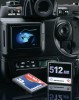
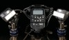
To improve image quality, various modifications in these systems have been developed (ie, diffusors [PTJ Diffusor Systems, PTJ International, Houdemont, France], macro lenses with an integrated ring flash [Kodak DX7590 Dental Digital Camera Kit, Kodak Company, Rochester, NY], and close-up lenses for improved magnification with a macro flash [Minolta Dimage 7, 7 iHi, A1, A2 Konica Minolta USA, Whitsett, NC]). For more predictable results in dental photography, however, a professional digital SLR camera is the system of choice (Figure 1).
A better understanding of digital photography can be ascertained from knowledge of the function and operation of the conventional film-based (ie, 35 mm SLR) camera system in comparison to the digital (ie, 35 mm digital SLR) camera system. The conventional 35 mm camera system creates an image by using light to activate the film through a chemical reaction. Light-sensitive molecules in the film emulsion are electrically charged in proportion to the amount of light that strikes each area of the film.9 Later, during the film development process, each charged molecule is enlarged and stained to become a grain (ie, the basic visible unit of film image detail). Together the grains combine to collectively compose the photographic image.
The digital 35 mm camera system uses light to activate a solid-state sensor through an electrical reaction. A charge coupled device (CCD) or a complementary metal oxide semiconductor (CMOS) photodiode detector stores an electric charge in proportion to the amount of light that strikes each portion of the sensor. The image is initially converted into dots of digital color information that combine to create the final image. Each dot of color data represents a picture element or “pixel” (ie, the basic visible unit of digital image detail).10,11 The greater the number of CCD or CMOS elements, the better surface detail and image quality recorded.11
During the digital image capture process, the sensor elements detect and convert light stimulation into an electrical analog signal. The analog signal is then analyzed and converted into computer-readable digitized binary code.9,12 The better the resolution of the analog-digital converter, the greater the number of luminance levels that can be distinguished. For example, a digitizer with an eight-bit resolution can convert the analog signals produced by the photo sensor into 28 digital values, allowing 256 levels of light to be distinguished.
The light-sensing electrodes of the digital sensor (ie, CCD or CMOS) are able to measure brightness levels but cannot measure wavelength (hue) differences.8 The sensor elements achieve color discernment by placing an ordered mosaic of red, green, and blue filters over the entire sensor (Figure 2). Each filter only allows its specific wavelength of color to pass through while blocking the complementary colors. The color level for the remaining two colors for any given pixel is interpolated from the data of adjacent pixels. A pixel with a color depth of eight bits has 256 possible values for each of its three color components (ie, red, green, blue). The combination of these three components in varying degrees of intensity provides 16.7 million (ie, 256 x 256 x 256) different color combination possibilities.9,13 Just as trilaminar photographic film influences the results for the conventional 35 mm camera system, the solid-state sensor determines the quality of the image at the heart of the digital 35 mm camera system. A digital 35 mm SLR camera system that has a resolution from eight to 12 megapixels will provide comparable image quality to slide film10 for printed images of 8" x 12" or less.
Clinical Applications of Digital Photography
The use of digital photography is becoming a standard of care for today’s modern dental practices14 through photographic documentation of clinical findings before initiating restorative treatment.15 Digital intraoral photography has greatly influenced the ease of documentation and storage of clinical images of specific clinical situations. There are numerous applications for digital photography in restorative dentistry. These include the following:
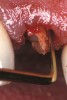
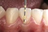
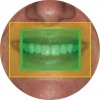
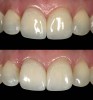
- Diagnosis and treatment planning: During the pretreatment assessment the digital photograph is an invaluable diagnostic tool. It provides the clinician, specialist, and technician with an instant visualization of the clinical setting without the need for the presence of the patient.9,16 In addition, preoperative digital photography can be used as a significant codiagnostic tool that often influences the patient to accept treatment17,18 (Figure 3).
- Legal documentation: Photographic images document pretreatment conditions as well as esthetic changes that were achieved through delivery of dental care. Potentially legally threatening clinical situations should be photographed, dated, and filed for easy retrieval.17-21
- Forensic documentation: Identification of human remains and the analysis of dental-related trauma (ie, human bite marks) through digital photographs can provide accuracy and reproducibility of detail.22-24
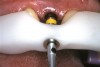
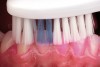
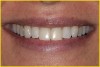
- Patient education and communication: A series of photographic images of previous treatment accomplished with other patients can provide a detailed explanation of a specific dental procedure and treatment alternatives.19,23 A combination of photographic description with oral and written information provides a more thorough informed consent.17,18,23-26 Furthermore, this visualization process stimulates patient awareness and involvement, which can advance the clinician/patient relationship27,28 (Figure 4).
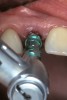
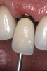
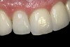
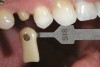
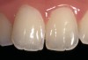
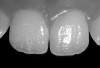
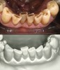
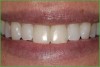
- Laboratory communication: Color photographs can illustrate shade comparisons with surrounding dentition and underlying substrates.29,30 Relative distributions of enamel staining, intensity of characterization, and the different degrees of translucency and opacity within the incisal edge can be adequately captured. Black and white photographic images can provide a visual description of surface texture in addition to a value comparison.9 Incisal edge position, as well as the relationship of the provisionals and final restorations to the contours of the lower lip and to the horizontal plane, can be evaluated. In addition, photographic postoperative critique can provide self-assessment feedback to each member of the restorative team and the opportunity to learn and improve from positive and negative results27 (Figure 5, Figure 6, Figure 7, and Figure 8).
- Professional instruction: Instructional photographs illustrating the armamentarium and protocol for specific clinical procedures can be used by auxillaries to improve organization and efficiency. In addition, photographic series can be used to describe a clinical condition or to communicate ideas and concepts with colleagues in lecture presentations, publications, and professional certification.21,31-33
- Insurance verification: Digital images of preexisting clinical conditions can indicate and reinforce treatment requirements and expedite authorization for an insurance claim.18-21,34
- Patient education and motivation: Periodic digital photographs of a patient’s clinical condition can provide immediate visual illustration of improvement or progression of a disease process (ie, caries, gingivitis, periodontitis)34,35 (Figure 9).
Components of the Digital Camera System
Obtaining a high-quality clinical image requires the use of proper photographic equipment. The basic components of the conventional and digital 35 mm camera system are similar; they include the camera body, lens, and the flash system. The lens focuses light within the camera that has been supplemented by the flash for intraoral purposes. The camera body coordinates the functions of the image capture. An evaluation of the basic components of the camera system (either film or digital) will provide necessary objective information for selection and subsequent application of a 35 mm system for clinical photography.
Camera Systems: Integrated Components
Film-based SLR and digital SLR camera systems use one lens for both image composition and image capture.15 This design, which allows direct viewing and focusing without parallax error, is ideal for dental photography.15,36,37
Lens Considerations
Dental photography requires magnified views of teeth, gingiva, and surrounding tissues. A lens selected for dental purposes must be able to capture diagnostic views of these structures while the clinician is positioned at a comfortable and convenient working distance from the patient. While many lenses can magnify the subject matter, macro lenses are able to capture an enlarged image of a subject while focusing at a close range. Today, most macro lenses have floating elements that are coupled to the distance setting and allow large magnification ratios that achieve good image quality. Macro lenses with a fixed focal length designation of 100 mm to 105 mm provide the ideal combination of magnification ability and working distance convenience for dental purposes. The quality of the lens has a significant influence on the sharpness, clarity, and ultimate quality of the final image.8
For close-up dental imaging, consideration must be given to two interrelated measurements—magnification and the magnification ratio. In photography, magnifying an image requires extending the lens forward, away from the sensor or film plate. The more a subject is magnified, the larger it is projected on the sensor and, thus, the larger it appears in the final image. The magnification ratio is the ratio of the size of the image projected on the sensor compared to the actual size of the object. A magnification ratio of 1:10 means the image on the sensor is one-tenth life size, while a 1:1 magnification ratio signifies a life-size image on the sensor. The lens must have 1:1 to 1:10 magnification settings to ensure reproducible images. The 1:1 setting is ideal for close-up imaging of teeth and will generally include the four maxillary incisors on the sensor. The 1:10 setting is useful for full-face views.
In a digital 35 mm camera system the sensor size has an influence on the magnification produced by a lens. The size of the sensor in most digital SLR cameras (approximately 16 mm x 24 mm) is significantly smaller than the size of a single frame of 35 mm film (24 mm x 36 mm). The lens will project the same size image in the back of the camera, regardless of whether the capturing media is film or an electronic sensor (Figure 10a, Figure 10b, Figure 10c, and Figure 10d). The digital sensor, however, is much smaller. Therefore, the captured image in most digital SLR cameras is cropped. Because a smaller portion in the center of the focused image is captured and then expanded to full size when it is viewed, the effective magnification of the lens is increased when using a digital SLR system. The true magnification created by the size of a digital sensor is approximately 1.5 times the designated magnification that would be achieved with film. The same macro lens set to a magnification ratio of 1:2 while mounted on a film camera would have to be set to a magnification ratio of 1:3 to capture the same magnification that appears while mounted on a digital camera. Cameras with full-frame sensors (ie, sensors that match the 24-mm x 36-mm dimensions of film) avoid this magnification effect.
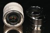
To create images with magnification ratios that exceed 1:1, additional attachments can be added to the lens. A teleconverter is a cylinder with light-focusing lens elements that can be placed between the lens and camera body to multiply the effective focal length of the lens. This effect provides greater magnification for the image at the same working distance. Unfortunately, this increase in magnification comes at the expense of diminished light reaching the sensor. The loss of light requires an adjustment to achieve the proper exposure. Additionally, teleconverters can cause some degradation in the sharpness of the image. An extension tube is also a cylinder that is mounted between the lens and camera that functions to move the lens farther away from the focal plane (ie, the film or digital sensor). Unlike the teleconverter, extension tubes are hollow without any lens elements (Figure 11). While extension tubes are often used to decrease the minimum working distance of a lens (ie, allow the photographer to gain a larger image by moving closer to the subject), they do provide some increase in magnification without a change in working distance. Extension tubes cause less light loss than teleconverters, with no degradation in the crispness of the final image, but the camera can no longer be focused at infinity, and some exposure adjustments are still required.
Light and Electronic Flash Systems
Photography has been described as “painting with light.”8 Proper illumination is one of the most significant factors in achieving a quality image. Because natural ambient light is inadequate to illuminate the dark shadows in most intraoral photographic situations, the most practical light source comes from a supplemental electronic flash source. An electronic flash can provide light with neutral color temperature, short duration of flash, and relatively high light output. These capabilities allow adequate exposure with low heat generation for patient comfort.8 Modern camera systems can be set for a white balance that matches the color quality of the flash.
In flash photography, the lighting effect is dependent upon the form and arrangement of the flash sources. There are three types of electronic flash system configurations available for dental photography (Figure 12):
- Ring flash light source system: The favorite among inexperienced dental photographers, it is considered the universal flash system for general macrophotography.38,39 This system furnishes either a single ring flash tube or individual sector flash tubes that surround the lens. The light completely surrounds the optical axis and is generally slightly in front of the lens so that it eliminates all shadows. The specular or mirror-type reflection created by this type of flash tends to eliminate shadows in the image. The advantage of this flash system is that objects in the oral cavity can be evenly illuminated without shadows. As a result, inexperienced members of the staff can readily use the ring flash configuration to achieve acceptable results. The disadvantage in the reduction of shadows is that the image may appear to “flatten out” with reduced discernable contours.
- Point flash light source system: This provides a single strobe light source mounted to one side of the lens. The isolated light can be moved to different positions around the lens to provide a directional light from different angles. Photographic compositions for frontal, right lateral, and left lateral views require the flash to be placed at the 12, 9, and 3 o’clock positions, respectively.8 Control of the light direction allows shadows to be cast by the three-dimensional topography of the objects in the scene. The appearance of shadows improves the visual definition of contour and texture to emphasize the apparent depth within the image. The advantage of this flash system design is its ability to record surface texture detail and contour. However, it is suggested that multiple images with several flash positions be taken to establish adequate information. This type of flash system requires considerable experience and additional set-up time to maneuver the flash position before each exposure.
- Twin flash light source system: Its configuration consists of two flash units that are mounted next to the lens in one of two designs. The first has two fixed strobes that are mounted in stationary positions on either side of the lens. Although this twin flash system may look similar to a ring flash, the light is only emitted from two vertically aligned tubes to the left and right of the lens with no light coming from the top or bottom. The second design uses two moveable flash strobes that are mounted further from the lens on moveable arms that can be placed in variable custom positions around a circular mounting bracket. The light sources can be positioned to create custom mild shadowing to reveal texture with depth and lifelike effects. Mastering the use of this lighting system will yield professional photographic results (Figure 13). While requiring more experience and thought for proper use, the twin flash design system may offer the best combination of soft, uniform illumination (Figure 14) because it simultaneously reveals surface detail, color transitions, translucency variations, and crack lines.14
Camera Body Considerations
A digital camera body is equivalent to the dashboard of a car. Both possess several knobs, switches, and dials to select settings and control performance. In addition, each possesses indicators to inform the operator about current conditions and potential problems. As with car amenities, the features of different camera bodies vary in sophistication.
The durability of the materials used in the construction of internal components, extremely rapid autofocusing systems, fast multiple exposure options, and increased size of the sensor are examples of high-end features that increase the cost of production and the price of the camera. These features are appropriate for individuals planning to do action photography or imaging in variable lighting conditions. Very few of these options, however, are necessary for the type of imaging performed in dentistry. For dental imaging, all features necessary for an excellent photograph can be obtained in camera bodies currently costing between $800 and $1,600. In prioritizing equipment purchase decisions, the best dental images would result not from acquiring the most expensive camera body, but from investing in high-quality lens and flash components.8 Most manufacturers of 35 mm digital camera systems have designed the lens mount to be able to receive and use the same lens and flash components that fit previous film-based systems.
Regardless of the number of complex capabilities a camera body may possess, the most critical and fundamental role is that of exposure control (ie, managing the amount of light that enters the lens and exposes the sensor or film). The objective in regulating the exposure is to create an image in which there is discernable detail in all the tones— both light and dark tones—throughout the scene.15 In indoor, flash-dependent photography (eg, digital dental photography), the amount of light falling on the sensor is determined by three factors: the aperture diameter of the lens, the duration of the exposure, and the relative sensitivity setting of the camera.15
The aperture is the size of the hole through which light enters the camera. An iris within the lens constricts in varying amounts to reduce the opening as needed when the image is captured. The specific size of the aperture is called an “f-stop” and is calculated as the ratio of the diameter of the lens opening to the lens focal length. For example, f-16 corresponds to an aperture diameter that is 1/16th of the focal length of the lens. For a 100 mm lens, f-16 would correspond to an aperture diameter of 6.25 mm, while an aperture of f-4 with the same lens would produce a diameter of 25 mm. The aperture number indicates the number of times the aperture diameter fits in the focal length of the lens (ie, f-4 = 4 x 25 mm; f-22 = 22 x 4.54 mm). Larger aperture numbers (eg, f-22, f-32) indicate smaller apertures and therefore less light reaching the sensor (Figure 15).
In addition to controlling the amount of light that enters the camera, the aperture also affects the amount of the scene that appears to be in focus. Light bends as it passes through the lens to be focused on the sensor. Because there is a greater curvature toward the edge of the lens than toward the center, photons passing through the edge are refracted more than those traveling through the center. When a small diameter aperture is used, light toward the edge of the lens is blocked, while light in the center passes to the sensor. As a result, more of the scene in front and behind the actual focal point appears to be in focus as well. The amount of the scene that appears to be in focus is called the depth of field. When the f-stop setting is higher, the aperture diameter becomes smaller and the depth of field is greater. For dental photograph applications, the clinician should maximize the depth of field by using the minimum aperture diameter possible. To complete the proper exposure, the aperture must be coupled with the proper exposure time and camera sensitivity. All exposure management strategies require some form of light measurement to determine the proper exposure.
Reflective Exposure Metering
Exposure metering is the process of objectively sensing light to calculate the proper exposure setting.15 The capability of a camera to monitor the amount of light coming “through the lens” is known as TTL. As a matter of convenience, photographers often use the TTL feature of their cameras to perform this measurement. TTL metering is a reflective technology; the amount of light entering the camera is determined by the amount of light that reflects off the subject.15
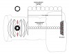
Most advanced 35 mm digital cameras offer a choice of three geometric configurations for TTL metering: spot, center-weighted, or matrix (Figure 16). With each of these systems, the camera measures the amount of light reflecting off the subject in trying to determine the proper exposure for that scene. Spot metering measures a small area of the scene (ie, usually 2% or less of the entire image area).1 Some camera bodies have a selector mechanism that allows the clinician to choose which specific spot within the viewfinder is activated for light measurement. Center-weighted metering evaluates the light reflected from the entire scene, but gives priority to a defined area in the center of the frame with less attention to the corners and edges.15,38 Some camera systems have the capability of selecting the diameter of the activated, prioritized middle metering area in the viewfinder. Matrix metering measures the entire frame by dividing it into segments. Each segment is evaluated and then compared against a proprietary database library of anticipated image algorithms to yield the final averaged reading. The photographer should select a metering configuration that evaluates the portion of the scene that he or she feels represents average luminance while ignoring areas of extreme highlights or shadows. Dental photography presents an obvious difficulty in that the most important portion of the image (ie, the teeth) is included in the lightest portion of the tonal range of the image.
Exposure Compensation
Regardless of the portion or proportion of the scene that is measured, contemporary camera systems are engineered to set the proper exposure for a subject that is approximately 18% gray in reflectivity.15 If the camera monitors an area of the image that is highly reflective, it will mistakenly perceive that a darker exposure is required and will inadvertently recommend settings for an underexposure. Conversely, if the metering system reads an area of the scene that is low in reflectivity, it will mistakenly discern that a lighter exposure is appropriate and inadvertently recommend settings for an overexposure.15
Unfortunately, clinicians are typically taking photographs of white teeth surrounded by dark shadows. Nothing in the scene approaches medium reflectivity. The high contrast between the dark and light areas of intraoral images presents a genuine problem in exposure determination.14,15
There is a potential for inconsistent and unpredictable exposure results when metering for dental photographs. If center-weighted or matrix metering strategies are selected, portions of the gingival and pharynx shadows will be evaluated along with the white teeth. Depending on the percentage of shadows that are included in the measurement, the results may be unpredictable and highly variable. Spot metering could guarantee that only a small portion of the teeth are metered, but it would still be inaccurate because teeth are much more reflective than 18% gray. With spot metering, the camera would have to be set to modify the calculated exposure to adjust for the bright luminance and high reflectivity of teeth.
The camera feature that allows an intentional modification in exposure metering is called exposure compensation. It allows the exposure recommendation made by the camera to be adjusted up or down to accommodate light or dark subject matter, respectively. When the exposure value (EV) is set to a negative number, the operator is notifying the camera that the subject matter being metered and photographed is dark (ie, reflecting less light than 18% gray).
In such an instance, a lower reading would be expected, and a darker exposure would be recommended and allowed. When the EV is set to a positive number, the clinician is alerting the camera that the subject matter being metered and photographed is light (ie, reflecting more light than 18% gray). In this case, a high reading would be expected, and a lighter exposure would be recommended and allowed. A positive exposure compensation setting would be required for spot metering highly reflective subjects such as white teeth. By warning the metering system that the subject is bright, the operator avoids an unwanted underexposure that would have been created by the preprogrammed assumption that subject matter was 18% gray.
Unfortunately, the amount of exposure compensation selected by the photographer requires some experience and is, at best, an estimation. Many camera bodies have an additional feature capability called bracketing. This setting helps the operator take a series of photographs—each with slightly raised and lowered exposure values (relative to the metered exposure)—with the expectation that one of them will be correct. The number of exposures in the series and the amount of EV variation in each interval is predetermined and set by the photographer. A full incremental value of +1 doubles the amount of light in the exposure while decrement of -1 halves the amount of light. Camera systems with the capability of 1/2, 1/3, or even 1/5 EV intervals in bracketing allow more sensitive and subtle exposure compensation.14
The use of bracketing can overcome the possible error in estimating how much exposure compensation is required for a particular scene by automatically producing several images of the same view, with each view having a slightly different exposure. Use of bracketing ultimately necessitates some additional image sorting time as the photographer reviews the images to select the best one and discard the rest.
Exposure Modes
After the light for an image has been measured, the camera must be set for those lighting conditions to create the proper exposure. Most digital SLR camera systems currently available on the market allow the operator to choose whether that role will be performed automatically by the camera or manually by the operator. With either method, the diameter of the aperture must be matched with the appropriate exposure time to achieve an acceptable result. A wide aperture combined with a short exposure can use the same amount of light as a narrow aperture combined with a long exposure.8 The key is to find the best combination for application in creating diagnostic dental images.
To resolve this issue, contemporary digital SLR cameras typically offer a selection among three automated exposure assignment alternatives. In the Program (P) mode, the camera selects both the aperture and exposure time for the photographer. In the Shutter Priority (S) mode, the photographer selects the desired exposure time while the camera selects the matching aperture. This mode is used typically to control the appearance of blur in a moving subject. For dental photography, however, the priority is to create the largest depth of field to maximize the amount of the scene that appears to be in focus. Because the aperture of the lens controls this outcome, the Aperture Priority (A) mode is the best automated exposure strategy for intraoral photographic applications. Apertures of f-5.6 to f-8 work well for full-face images. Aperture selections of approximately f-22 work well for smile views and full-arch views, while aperture settings of approximately f-32 maximize the depth of field for close-up views. In flash-assisted intraoral photography, the exposure time is a function of the length of the flash burst, not the duration of the shutter speed.8,15To use automated aperture-priority metering, the flash unit must be compatible with TTL technology.
Although some subjective conjecture is required to modify TTL technology with exposure compensation in photographing the high-contrast components of an intraoral scene, many new photographers conclude that automated exposure determination in aperture-priority mode allows them to create acceptable photographic images with a minimum initial learning curve.
Incident Exposure Metering
While automated exposure strategies in aperture-priority mode produce adequate results, special consideration in the use of spot metering, exposure compensation, and bracketing may all be required. Even then the results are somewhat subjective. The concept of using automated TTL technology in dental applications is fundamentally flawed because it is a reflective metering technology, which is affected by the reflective properties of the subject and assumes them to be equivalent to 18% gray (Figure 17a, Figure 17b and Figure 17c).
More precise results can be achieved with the use of a separate, hand-held light meter (Figure 17d). This device does not measure the amount of reflected light entering through the lens, but rather the amount of incident light falling on the subject. The advantage of this strategy is that the determination of the exposure is independent of and unaffected by the optical qualities of the subject itself.15 Dark objects will appropriately appear dark and light objects will correspondingly appear light.
Sophisticated digital SLR camera systems often offer a Manual (M) exposure mode to benefit from incident light metering. With this setting, the photographer sets both the aperture and the exposure time. This technique requires additional equipment and time commitment to learn the photographic principles for setting camera exposure manually. Ultimately, however, the exposure results are considerably more predictable and consistent, requiring significantly less time for trial-and-error experimentation to determine the correct settings with automated exposure compensation. The ideal method for determining the correct exposure setting for a specific dental scene is to use an incident light meter. The light meter measures the light falling on a subject and can establish the proper exposure setting from a desired magnification distance. This method eliminates any error that would occur from the varying reflective properties of the subject itself, but it requires a camera that has manual exposure capability to control the aperture opening and the flash output.15
Filmless Imaging: Viewing, Transmission, and Storage
In the past, film-based photography required film selection, film and processing costs, and waiting for the roll to end. After the shutter was released, there was minimal flexibility in photographic processing.38 Film development typically was out of the hands of the photographer. A consistent and trustworthy processing laboratory was required to collaborate in the production of the images. When returned, labeling and logging each photographic image (ie, slide or print format) was still required to retrieve the image for later viewing.
Times have changed; “the past has become the future.” Filmless imaging currently presents a new set of variables. Digital imaging requires the understanding and application of a new set of skills. Beyond mastering the camera, the photographer now also must “process” the images. The computer has replaced the darkroom. Color management of the camera, monitor, and printer all affect the color of the final images. Workflow decisions regarding color space, image size, formatting, and editing are now the photographer’s responsibility. The chore of labeling and logging images for storage and retrieval remains as important. In this “brave new world,”40 dental practitioners must remember that the ultimate goal of producing an excellent photograph should not be to enhance or disguise the clinical reality, but to accurately capture and share what their eyes see so they can learn from and improve it.41
Guidelines for Selection and Application of a Digital Camera System
This discussion has provided a description of the function, application, and basic components of the digital 35 mm camera system. In summary, the following table is provided for a comparison of digital camera systems designed for dental photography and as a guideline for their proper selection and application (Table 1).
Conclusion
Technological developments in the photographic process have continued to change and improve the practice of dentistry. Clinicians must now integrate existing photographic principles with today’s contemporary camera systems and computer software technology. This evolution to a contemporary photographic process is revolutionizing the way clinicians diagnose, treat, and communicate with patients and colleagues. In this technologically advancing profession, the clinician should consider using an objective strategy for the selection and application of any camera system.
References
1. Kravets TP. Documents on the History of the Invention of Photography. Leningrad, Russia: Soviet Academy of Science; 1949. Archived publication No. 7:360,361,380,388-389.
2. Humphrey SD. American Handbook of the Daguerreotype. 5th ed. New York, NY: Humphrey Publishing; 1858.
3. Hook SA. Early dental journalism: a mirror of the development of dentistry as a profession. Bull Med Libr Assoc. 1985;73(4):345-351.
4. Glenner RA, Davis AB, Burns SB. The American Dentist: A Pictorial History with a Presentation of Early Dental Photography in America. Missoula, MT: Pictorial Histories Publishing Co; 1990.
5. Henisch HK, Henisch BA. The Photographic Experience 1839- 1914: Images and Attitudes. University Park, PA: Penn State Press; 1994:216.
6. Mautz C. Biographies of Western Photographers. Nevada City, CA: Carl Mautz Publishing; 1997.
7. Laws R. The author’s guide to controlling the photograph. J Prosthet Dent. 2001;85(3):213-218.
8. Bengel W. Mastering Digital Dental Photography. 2nd ed. Chicago, IL: Quintessence; 2006.
9. Zyman P, Etienne JM. Recording and communicating shade with digital photography: concepts and considerations. Pract Proced Aesthet Dent. 2002;14(1):49-53.
10.Clark JR. Digital photography. J Esthet Restor Dent. 2004;16(3):147-148.
11.Hutchinson I, Williams P. Digital cameras. Br J Orthod. 1999;26(4):326-331.
12.Ahmad I. Digital and Conventional Dental Photography: A Practical Clinical Manual. Chicago, IL: Quintessence Publishing Co; 2004.
13.Milburn K. CliffsNotes: Taking and Sharing Digital Photographs. Hoboken, NJ: Hungry Minds-IDGB; 2000.
14.McLaren EA, Terry DA. Photography in dentistry. J Calif Dent Assoc. 2001;29(10):735-742.
15.Snow SR. Dental photography systems: required features for equipment selection. Compend Contin Educ Dent. 2005;26(5):309-310-316.
16.Gane D. Aesthetic success with the utilization of digital imaging. Pract Periodontics Aesthet Dent. 2000;12(4):407-408.
17.Goldstein MB, Young R, Bergmann R. Digital photography. Compend Contin Educ Dent. 2003;24(4):260-273.
18.Goldstein MB. Digital photography in your dental practice. The why’s, how’s, and wherefore’s. Dent Today. 2003;22(4):98-101.
19.Christensen GJ. Important clinical uses for digital photography. J Am Dent Assoc. 2005;136(1):77-79.
20.Pensler AV. Photography in the dental practice (I). Quintessence Int Dent Dig. 1983;14(7):745-751.
21.Fan PP. Choosing the right clinical camera. Part I. Oral Health. 1998;88(4):67-73.
22. Bernstein ML. The application of photography in forensic dentistry. Dent Clin North Am. 1983;27(1):151-170.
23. Wander P, Gordon P. Specific applications of dental photography. Br Dent J. 1987;162(10):393-403.
24. Levine LJ. Bite mark evidence. Dent Clin North Am. 1977;21(1):145-158.
25. Christensen GJ. Informing patients about treatment alternatives. J Am Dent Assoc. 1999;130(5):730-732.
26. Christensen GJ. Elective vs. mandatory dentistry. J Am Dent Assoc. 2000;131(10):1496-1498.
27. Terry DA, Moreno C, Geller W, et al. The importance of laboratory communication in modern dental practice: stone models without faces. Pract Periodontics Aesthet Dent. 1999;11(90):1125-1132.
28. Touati B. Esthetic Dentistry and Ceramic Restorations. London, UK: Dunitz; 1999.
29. Elter A, Caniklioglu B, Deger S, et al. The reliability of digital cameras for color selection. Int J Prosthodont. 2005;18(5):438-440.
30. Dunn JR, Hutson B, Levato CM. Photographic imaging for esthetic restorative dentistry. Compend Contin Educ Dent. 1999;20(8):766-774.
31.Swift EJ Jr, Quroz L, Hall SA. An introduction to clinical dental photography. Quintessence Int. 1987;18(12):859-869.
32.Pensler AV. Photography in the dental practice (II). Quintessence Int Dent Dig. 1983;14(8):855-858.
33. Tribe HE. Selecting and preparing illustrations for publication and presentation. Dent Clin North Am. 1983;27(1):95-107.
34. Strassler HE. Insights and innovations. J Esthet Dent. 1990;2(3):93-94.
35. Benjamin S, Aguirre A, Drinnan A. Digital photography enables better soft tissue screening, diagnosis, and case acceptance. Dent Today. 2002;21(11):116-121.
36. Daniels TE, Sherrill CA. Handbook of Dental Photography. San Francisco: University of California; 1974.
37. Eastman Kodak Company. Professional techniques in dental photography. In: Biomedical Photography: A Kodak Seminar in Print. Rochester, NY: Eastman Kodak Co; 1976:17-37.
38. Freeman M. Pro Digital Photographer’s Handbook. Asheville, NC: Lark Book; 2005.
39. Fan PP. Choosing the right clinical camera. Part II. Oral Health. 1998;88(5):35-42.
40. Astrachan A. Aldous Huxley’s Brave New World. Hauppauge, NY: Barron’s Educational Series; 1984.
41. Fan PP. Choosing the right clinical camera. Part III. Oral Health. 1998;88(6):35-42.
About the Authors
Douglas A. Terry, DDS
Assistant Professor
Department of Restorative Dentistry and Biomaterials
University of Texas Health Science Center at Houston
Houston, Texas
Stephen R. Snow, DDS
Visiting Faculty Member
UCLA Center for Esthetic Dentistry
Los Angeles, California
Director
PERFECT Perspectives Advanced Dental Seminars
Danville, California
Edward A. McLaren, DDS
Director
UCLA Center for Esthetic Dentistry
Los Angeles, California
Director
School for Esthetic Dental Design
School of Dentistry
University of California at Los Angeles
Los Angeles, California