You must be signed in to read the rest of this article.
Registration on CDEWorld is free. You may also login to CDEWorld with your DentalAegis.com account.
The use of cone-beam computed tomography (CBCT) has revolutionized the field of dentistry since the time of its introduction to the US dental market in 2001.1 Using a cone-shaped x-ray beam to create a 3-dimensional (3D) image of the teeth, jaws, and other surrounding structures, CBCT yields images that are much more accurate than traditional 3D radiographs, and it is much more efficient than earlier imaging modalities. Its multiple fields of view and the reduced radiation associated with its use have allowed clinicians to collect more appropriate data with CBCT.2
CBCT has a wide variety of applications, including diagnosis, treatment planning, and implant placement.3 When used as a diagnostic modality, CBCT can help dental clinicians detect and characterize caries and identify other conditions such as periodontal disease. CBCT images can also be used to plan treatments such as root canal therapy and tooth extractions, where it is important that tooth root morphology and canal shape be fully appreciated. In addition, CBCT can assist in accurate implant placement, as its detailed imaging of the jaw and surrounding structures helps ensure correct positioning of the implant.
The Rise of Implant Therapy, CBCT, and Intraoral Scanning
Dental implant surgery has emerged as the standard of care for the replacement of missing or extracted teeth in healthy patients. As of 2016, in the United States alone, more than
8 million adults older than 65 years were edentulous; those who were dentate had only 21 teeth on average.4 This surge in implant therapy has been directly related to a reduction in product cost.5 As the cost of dental implants has declined and the tools and skill sets of practitioners have improved, increasingly greater numbers of patients are receiving dental implant therapy as a permanent solution to replace their missing teeth. As a testament to the technological improvements in and concurrent increasing ease of dental implant procedures, general dentists in the United States have exhibited an increased interest in implant dentistry. In the author's opinion, this would not be possible without new technologies such as CBCT.
At the same time that CBCT was substantially enhancing the capabilities of dental radiology, another synergistic digital revolution was taking place with intraoral scanning (IOS). First developed by Dr. Francois Duret in the 1970s,6 IOS began to improve dramatically in the 2000s.7 With these advancements came a decrease in cost, making IOS an affordable alternative to traditional impression record taking. In addition to IOS, desktop scanning was enhanced as well, allowing clinicians to digitize analog impressions or models. Combining CBCT and IOS has enabled increased efficiency and reduced treatment times across various dental procedures, most notably dental implant placement.
USE OF CBCT AND IOS IN GUIDED IMPLANT SURGERY
While conventional free-handed and template-assisted implant placement approaches have many advantages,8 guided implant placement has become widely accepted as the most accurate method to use across every stage of treatment, from planning to execution. Guided surgery, whether static or dynamic, has numerous applications, ranging from implant placement of a single tooth to advanced facial reconstruction.
Among the more popular dental implantology procedures of the past few decades are immediate single-tooth and full-arch replacement therapies.9 To achieve optimal outcomes, these procedures require a high-quality CBCT machine that can produce a digital DICOM file along with a digital impression in a digital STL, Ply, or obj file.10 In order to properly plan or create a surgical guide, the DICOM file and the digital impression file are merged in a planning software.11
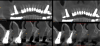
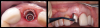
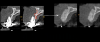
Importantly, patients for whom implant placement is being planned may have previously undergone root canal treatment utilizing radio-opaque materials or have amalgam, metal, or metallo-ceramic restorations, or they may even have previous implants. When x-ray beams pass through these radio-opaque objects, the resulting CBCT images often have metallic scatter (Figure 1, left panel). The artifacts or noise created by the metallic or metallic-like substances degrade the image quality and induce cupping or streaks. This can be particularly troublesome when the clinician is attempting to diagnose dental conditions or to fabricate surgical guides.
Previous CBCT softwares utilized the FDK (Feldkamp, Davis, and Kress) algorithm or SART (simultaneous algebraic reconstruction technique ).12 For many years, the quality of CBCT scans required additional steps to reduce the amount of scatter; often a tray or fiducial device would be required in the CBCT patient capture and again in a standalone capture. However, advancements in CBCT such as metal artifact reduction (MAR)13 (Figure 1, right panel) and beam hardening removal have helped address these challenges in obtaining high-quality scans. Projection-based MAR algorithms act in projection space and replace corrupted projections caused by metal with interpolation from neighboring uncorrupted projections. By reducing scatter and artifacts, these enhanced tools of MAR allow for a simplified matching between 3D radiography and the digital impressions, allowing users to expedite planning and treatment as a whole. Once the files have been merged, proper treatment planning can begin.
Case Study 1: Guided Implant Surgery in Conjunction With Partial Extraction Therapy
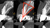
Evaluation of a single site can be simplified using the "triangle of bone" concept.14 In the author's practice, a 48-year-old male patient presented for a routine emergency recementation visit, at which time a root fracture was noted on the palatal side of the patient's root. The crown was temporarily recemented, CBCT imaging was performed (Figure 2), and the patient was evaluated for tooth replacement with a dental implant. A triangle was drawn in the cross-sectional CBCT image to determine the proper implant placement and analyze the future implant in a restorative-driven fashion.15 Careful evaluation of this cross-section revealed a thin buccal plate associated with the endodontically treated root. This finding indicated that the buccal wall would likely be fractured during extraction, which would lead to a buccolingual collapse16of the hard and soft tissues. To avoid this risk, partial extraction therapy, a technique used to preserve the buccal plate by carefully removing contents of the root and leaving the buccal segment,17-19 within the triangle of bone was planned.20
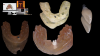
After incorporating the IOS, a computer-
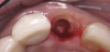
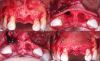
aided design software (360 DPS, 360 Imaging; alternatively: 3Shape Implant Studio®, 3Shape; Blue Sky Plan®, BlueSkyBio) was utilized to create a surgical guide and immediate restoration (Figure 3). The guided surgical procedure was uneventful. The palatal portion was sectioned from the buccal wall and extracted using a root membrane kit (Figure 4). The remaining root was trimmed and shaped to create space for an immediate implant and prosthetic abutment. An implant (AnyRidge®, MegaGEN; alternatively: Neodent® Grand Morse™, Straumann; NobelReplace®, Nobel Biocare) was placed, the gap junction was grafted, and a prefabricated zirconia abutment was seated (Figure 5). A provisional restoration was placed and cemented using a temporary cement and allowed to heal (Figure 6). Initial torque and implant stability quotient (ISQ) data (Osstell) were recorded to be evaluated for final restoration at a later time.
Three months postoperatively, the patient returned for final impressions. Radiographs and ISQ measurement revealed excellent healing, and intraoral inspection showed proper emergence profiling with adequate soft tissue development. A final impression was performed and a final crown was inserted at the 3 month follow-up visit (Figure 7). Long-term 5-year follow-up revealed excellent stability. The use of CBCT and IOS reduced the duration of treatment and the number of office visits for the patient.
Discussion
The use of CBCT allowed partial extraction therapy to be planned, as well as dental implant placement, with extreme accuracy. Furthermore, the MAR feature of the CBCT allowed clarification of the borders of crowns, root canal fillers, and the thin buccal plate of bone, which are all essential to appreciate when working on such a small scale. IOS was used to help with the guide fabrication prior to surgery and prosthetic design during restoration. Both of these technologies allowed treatment to be completed without error, from the design of the guide, to the implant placement, to the fit and appearance of the final prosthesis.
Case Study 2: Guided Implant Surgery Utilizing a Staged Conservative Approach
Often patients present with inadequate available bone for dental implant placement. Fig-
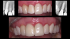
ure 8 depicts a 68-year-old male patient with two failing central incisors that required extraction. Before his visit with the author's practice, the patient had consultations with multiple clinicians and was given options of a dental bridge, a removable prosthesis, or dental implants that would have resulted in poor cosmetic outcomes.
After obtaining an initial CBCT image and IOS, it was apparent that there was a lack of available bone, a lack of buccal plate, and an excess of granulation tissue around the failing central incisors. Although immediate dental implantation was a potential option, the patient decided against this approach. A staged conservative approach was selected owing to the lack of available bone and extent of pathology that were exhibited by these incisors. Extractions and debridement followed by guided bone regeneration were performed. A large laminar membrane (Maxxeus; alternatively: Lamina®, Osteobiol®, Technoss Dental; Maxgraft® cortico, Botiss Dental, Straumann) anchored by intraoral tacks aided in stabilizing the membrane and graft (Figure 9). The graft was covered with several layers of platelet-rich fibrin, and primary tension-free closure was obtained.
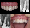
Four and a half months later, a new CBCT image (Figure 10) was captured, along with new IOS. Implant surgery was planned using planning software R2GATE®, MegaGEN; alternatively: Blue Sky Plan®, BlueSkyBio; RealGUIDE™ Plan, RealGUIDE) and a surgical guide was fabricated. A minimal flap approach was utilized for the placement of the two implants (AnyRidge®, MegaGEN; alternatively: Neodent® Grand Morse™, Straumann; NobelReplace®, Nobel Biocare), and the implant sites were prepared using Densah burs (Figure 11). Torque and ISQ were recorded to assist in determining the timing for the final restorations. Struts extending from the surgical guide were designed in the location of the previously placed tacks, allowing for simple access and their removal. No immediate temporization was attempted; however, anatomically designed healing abutments were used to develop the soft tissues.
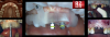
The patient returned for evaluation 2 months after implant placement. Radiographs and ISQ measurements were obtained, and intraoral scans using IS 3700 (DEXIS; alternatively: i700, Medit; Trios 5, 3Shape) were sent to the laboratory to fabricate the final restorations. Individual screw-retained crowns were fabricated and inserted at the follow-up visit (Figure 12, bottom left panel).
At the 6 year follow-up visit, radiographs revealed successful long-term stability of the restorations (Figure 12, bottom right panel). The use of digital technologies reduced the duration of treatment, and the results that were achieved using a conservative approach for greater predictability greatly surpassed the patient's expectations.
Discussion
CBCT machines are often used to take images of recently grafted sites in order to assess the extent of bone growth and ossification. In this case, the author was able to determine that the bone grafting procedure was successful and that the site was ready to undergo implant placement within 4.5 months of surgery. The newer and more discerning CBCT machines help the clinician avoid reentering a site too prematurely, which can jeopardize the bone graft and/or implants. As discussed in Case Study 1, the IOS was used to help design a surgical guide and accurately fabricate final prostheses.
Case Study 3: Full-Arch Rehabilitation
Full-arch replacement can implement additional features of CBCT, such as extraoral facial scanning. Extraoral facial scanning can be integrated into CAD/CAM software, thereby replacing the use of inaccurate 2-dimensional images with 3D representations to determine lip position, vertical dimension, and smile line, among other facial parameters.
A 66-year-old male patient presented to the clinic with failing maxillary dentition. Along with a plan to address the extensive decay and tooth mobility, the patient expressed a desire for a cosmetic outcome. Treatment options included extractions with implant placement, extractions with removable prostheses, and periodontal maintenance with a guarded long-term prognosis. The patient elected to undergo extraction of his maxillary teeth, with implant placement and a fixed full-arch prosthesis (All-on-X).
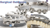
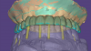
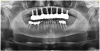
An All-on-X treatment approach for a patient requiring full-arch rehabilitation involves a number of considerations with regard to fixed restorative options. Fixed restorative options include FP1 - tooth replacement only; FP2 - tooth elongated or slight pink replacement; and FP3 - tooth and tissue replacement.21 FP3 requires significant bone reduction to create the restorative space required to simulate both tooth and tissues. While FP3 is easier to accomplish, the amount of bone reduction required would potentially jeopardize the esthetic outcomes desired by the patient. FP1 may allow a better esthetic appearance, but the results can be difficult to achieve; without controlling the amount of bone reduction required for restorative space, the outcome may head from an FP1 to an FP2/3. Utilizing the advanced tools of the CS MAR along with IOS and facial scanning using CS 9600 (Carestream Dental; alternatively: RAYSCAN Studio, Ray America; Viso® G7, Planmeca) (Figure 13), a proper 3D simulation was created and a plan for the full-arch rehabilitation was developed. For this patient, the plan included incorporating partial extraction therapy for buccal plate preservation and fabrication of a scalloping guide to control the restorative and esthetic space.
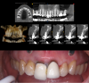
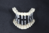
A stackable metallic guide22 (Figure 14) (Chrome GuideSmile, Chrome; alternatively: stackable non-metallic guide, Surgical Guide and Start Bit, NDX nSequence; stackable non-metallic guide, Anatomic Guide™, 3Sixty) was created through the use of planning software (Blue Sky Plan®, BlueSkyBio; alternatively: R2GATE®, MegaGEN; RealGUIDE™ Plan, RealGUIDE). A pin installation guide that seats over the existing teeth was used to install a foundational base for which the remaining stackable guides could be attached. The attachments seat and lock by means of a Swiss locking mechanism. After PET was performed and the remaining root sections were shaped and cleaned, a scalloping guide was inserted to aid in hard tissue sculpting. This sculpting is predetermined by the heights of contour of the prefabricated provisionals incorporating desired emergence profiles. Surgical guidance of subsequent drills and implants (AnyRidge; alternatively: Neodent® Grand Morse™, Straumann; NobelReplace®, Nobel Biocare) was delivered using the osteotomy guide. Multi-unit abutments were inserted to create passivity and path of insertion. Temporary cylinders were attached, and the prefabricated metal-
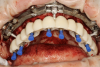
reinforced provisional (Figure 15) was luted in the mouth with intraoral pick-up material, creating a screw-retained provisional appliance (Fig-
ure 16). The provisional was removed, and flowable composite was added to the intaglio to help guide and shape the tissue for proper emergence profiles. Gap grafting was completed, and the provisional was reinserted. The patient was given proper postoperative instructions, including dietary plans to eat soft foods only. The surgery was unremarkable, and the postoperative results were as predicted.
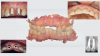
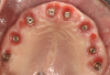
Three months postoperatively, the patient was recalled for a follow-up visit. The soft and hard tissues were preserved (Figure 17), and the patient reported that he was extremely pleased with the current provisional. Final extensive digital impressions were taken. Photogrammetry23,24 was used to capture implant position via domino-like scan flags. A fit verification jig (iJIG™, Roe Dental; alternatively: verification jig, Absolute Dental Services; verification jig, Technique Porcelain Studios) scan25 of the provisionals with scan analogs attached was obtained to capture the shape of the provisionals related to implant position (Figure 18). To capture the soft tissue, IOS using scan bodies was incorporated. This imperative scan will show any discrepancies or gaps between the provisional and soft tissue. The opposing intraoral scan and occlusion were captured as well.
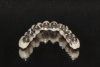
A final prosthesis was created using CAD/CAM software (Exocad software, Exocad; alternatively: 3Shape Design Studio, 3Shape; Medit Design, Medit) (Figure 19). After analyzing and adding changes to the incisal edges virtually, the final full monolithic zirconia prosthesis was milled. At the insertion visit, no adjustments were required. At the 3 year follow-up visit, excellent maintenance of hard and soft tissues was observed, and the patient reported that he was extremely satisfied with the results (Figure 20).
Discussion
The CBCT machine was critical to this case, by serving as a diagnostic device to appreciate the patient's anatomy and pathology, and by acting as a digital articulator by providing a facial scan of the patient. By combining these data with IOS, the author was able to quickly and accurately design the implant placement and multiple prostheses throughout treatment, ultimately accomplishing a successful outcome in fewer appointments.
CONCLUSION
Overall, the use of CBCT has revolutionized dentistry. This digital technology has allowed clinicians to obtain highly detailed images of the teeth, jaws, and surrounding structures that are more accurate than images produced by earlier diagnostic modalities, and with much greater efficiency. The new features incorporated in CBCT software discussed in this article (specifically, metal artifact reduction and facial scanning) have increased the versatility of CBCT across a wide range of applications, which range from diagnosis and treatment planning to implant surgery. Guided implant placement has been greatly enhanced by the use of CBCT. Particularly when combined with IOS, CBCT has resulted in improved outcomes and greater patient satisfaction with both single-tooth and full-arch replacement via guided surgery, by reducing treatment time and increasing predictability. As digital technologies such as CBCT continue to advance, further expediting the treatment planning and execution of implant placement-and ultimately resulting in the long-term stability of implant-supported restorations-professionals and patients alike will reap the benefits.
About the Authors
Isaac D. Tawil, DDS, MS
MINEC Ambassador (MegaGen International Network of Educators and Clinicians)
Diplomate, International Academy of Dental Implantology and International Academy for Dental Facial Esthetics
Fellow, International Congress of Oral Implantologists
Private Practice, Brooklyn, New York
Michael Erdos, DDS
Member, American Academy of Implant Dentistry
Member, Academy of General Dentistry
Member, American Academy of Clear Aligners
Private Practice, Brooklyn, New York
DISCLOSURE: Dr. Tawil and Dr. Erdos received an honorarium from Carestream Dental for writing this article.
References
1. Hatcher DC. Operational principles for cone-beam computed tomography. J Am Dent Assoc.2010;141 (suppl 3):3S-6S.
2. Scarfe WC, Farman AG, Sukovic P. Clinical applications of cone-beam computed tomography in dental practice. J Can Dent Assoc. 2006;72(1):75-80.
3. Benavides E, Rios HF, Ganz SD, et al. Use of cone beam computed tomography in implant dentistry: the International Congress of Oral Implantologists consensus report. Implant Dent. 2012;21(2):78-86.
4. Centers for Disease Control and Prevention. Oral Health Surveillance Report: Trends in Dental Caries and Sealants, Tooth Retention, and Edentulism, United States, 1999-2004 to 2011-2016. Atlanta, GA: Centers for Disease Control and Prevention, US Dept of Health and Human Services; 2019.
5. Tunchel S, Blay A, Kolerman R, Mijiritsky E, Shibli JA. 3D printing/additive manufacturing single titanium dental implants: a prospective multicenter study with 3 years of follow-up. Int J Dent. 2016;2016:8590971.
6. Duret F, Blouin JL, Duret B. CAD-CAM in dentistry. J Am Dent Assoc. 1988;117(6):715-720.
7. Mangano F, Gandolfi A, Luongo G, Logozzo S. Intraoral scanners in dentistry: a review of the current literature. BMC Oral Health. 2017;17(1):149.
8. Rinaldi M, Ganz S, Mottola A. Computer-Guided Applications for Dental Implants, Bone Grafting, and Reconstructive Surgery (adapted translation).1st ed. Elsevier: 2015.
9. Mello CC, Lemos CAA, Verri FR, Dos Santos DM, Goiato MC, Pellizzer EP. Immediate implant placement into fresh extraction sockets versus delayed implants into healed sockets: a systematic review and meta-analy-sis. Int J Oral Maxillofac Surg. 2017;46(9):1162-1177.
10. Ganz SD. Conventional CT and cone beam CT for improved dental diagnostics and implant planning. Dent Implantol Update. 2005;16(12):89-95.
11. Franchina A, Stefanelli LV, Maltese F, et al. Validation of an intra-oral scan method versus cone beam computed tomography superimposition to assess the
accuracy between planned and achieved dental implants: a randomized in vitro study. Int J Environ Res Public Health. 2020;17(24):9358.
12. Després P, Jia X. A review of GPU-based medical image reconstruction. Physica Medica. 2017;42:76-92.
13. Bechara BB, Moore WS, McMahan CA, Noujeim M. Metal artefact reduction with cone beam CT: an in vitro study. Dentomaxillofac Radiol. 2012;41(3): 248-253.
14. Ganz SD. The triangle of bone-a formula for successful implant placement and restoration. Implant Soc. 1995;5(5):2-6.
15. Ganz S. The reality of anatomy and the triangle of bone. Inside Dent. 2006;2(5):72-77.
16. Araújo MG, Lindhe J. Dimensional ridge alterations following tooth extraction. An experimental study in the dog. J Clin Periodontol. 2005;32(2):212-218.
17. Gluckman H, Salama M, Du Toit J. Partial extraction therapies (PET) Part 1: maintaining alveolar ridge contour at pontic and immediate implant sites. Int J Periodontics Restorative Dent. 2016;36(5):681-687.
18. Hürzeler MB, Zuhr O, Schupbach P, Rebele SF, Emmanouilidis N, Fickl S. The socket-shield technique: a proof-of-principle report. J Clin Periodontol. 2010;37(9):855-862.
19. Siormpas KD, Mitsias ME, Kotsakis GA, Tawil I, Pikos MA, Mangano FG. The root membrane technique: a retrospective clinical study with up to 10 years of follow-up. Implant Dent. 2018;27(5):564-574.
20. Ganz S, Tawil I, Mitsias M. The root membrane concept: in the zone with the "triangle of bone." Dentistry Today. 2021;36.
21. Misch CE. Contemporary Implant Dentistry.2nd ed. St Louis, MO: Mosby; 1999:68-70.
22. Ganz SD, Tawil I. Full-arch implant surgical and restorative considerations: utilizing a full template guidance technique. Dentistry Today. Published September 2019. https://www.dentistrytoday.com/full-arch-implant-surgical-and-restorative-considerations-utilizing-a-full-template-guidance-technique/. Accessed January 24, 2023.
23. Peñarrocha-Oltra D, Agustín-Panadero R, Bagán L, Giménez B, Peñarrocha M. Impression of multiple implants using photogrammetry: description of technique and case presentation. Med Oral Patol Oral Cir Bucal. 2014;19(4):e366-e371.
24. Tawil I. How dynamic navigation can improve accuracy and minimize errors. Compend Contin Educ Dent. 2021;42:430-435.
25. Ganz SD, Tawil I. Full-arch implant surgical and restorative considerations: innovative digital workflow using a verification jig with teeth. Dentistry Today. Published January 1, 2020. https://www.dentistrytoday.com/full-arch-implant-surgical-and-restorative-considerations-innovative-digital-workflow-using-a-verification-jig-with-teeth/. Accessed January 24, 2023.